
2023 Chicago Regional Bridge Building Contest Specifications
These rules have been developed by the Chicago Regional Bridge Building
Committee for the Forty-Seventh Chicago Regional Bridge Building
Contest to be held on Tuesday, January 31, 2023 at Illinois Institute of
Technology, Chicago IL 60616, USA. If you have a question about these
rules, FIRST take a look at the list of Frequently Asked Questions (FAQ) to see
if the answer is already there. If you have read the FAQ, and still have
a question about the contest rules, then you may contact the Chief
Judge, Jamal Grainawi at
Jamal.grainawi@wsp.com.
For questions on any contest topic EXCEPT the rules please contact
Prof. Carlo Segre at
segre@iit.edu.
The object of this contest is to see who can design, construct and test
the most efficient bridge within the specifications. Model bridges
are intended to be simplified versions of real-world bridges, which are
designed to permit a load to travel across the entire bridge. In order to
simplify the model bridge design process, the number of loading positions
is reduced, and to allow the contest to proceed in a reasonable amount of
time, only one loading position is actually tested. These simplifications
do not negate the requirement that the bridge must be designed to accept a
load at any of the positions. Bridges determined by the judges to not
meet this requirement will be disqualified and tested as unofficial
bridges.
1. Materials
-
The bridge must be constructed only from 3/32-inch square
cross-section basswood and any commonly available adhesive.
-
The basswood may be notched, cut, sanded or laminated in any manner.
-
No other materials may be used. The bridge may not be stained,
painted or coated in any fashion with any foreign substance.
2. Construction
-
The bridge mass shall be no greater than 25.00 grams.
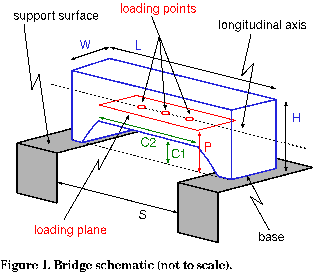
-
The bridge (see Figure 1) must span a gap (S) of 300. mm,
be no longer (L) than 400. mm,
be no taller (H)
than 180. mm above the support surface, and no wider
(W) than 70. mm. It must have a
horizontal loading plane that is a maximum height
(P) of 80. mm above the
support surfaces. The bridge structure may not project below the
support surfaces.
-
The bridge must be constructed to provide a horizontal support
surface for the loading plate and rod at each of the three
possible loading positions. These three positions, at the
at the mid-span of the bridge and 60. mm to either side of
the center, will be clearly and consecutively labeled "1,
2, 3" from either end of the bridge by the participant
before check-in (see 3b). The bridge structure must
allow the loading rod (see 3a) to be mounted from below.
-
The bridge must have a minimum clearance
(C1) of 60. mm in height above
the support surfaces. This clearance extends a minimum length
(C2) of 160. mm and be centered
on the mid-span of the bridge. No part of the bridge structure may be
built into this clearance area, and a 60. mm high by
160. mm wide block must pass cleanly under the bridge.
3. Loading
-
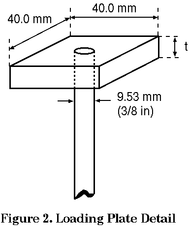
The load will be applied downward, from below, by means of a
40. mm square plate (see Figure 2). The plate will be
(t) of at least 6 mm but less than 13 mm and will
have a 9.53 mm (3/8 inch) diameter threaded rod eyebolt
attached from below at its center with a standard hex nut. The plate
will be horizontal with two sides parallel to the
longitudinal axis of the bridge.
-
The three loading positions will be located on the horizontal loading
plane (P). The center position
(numbered "2") will be located at
the center point of the bridge. The other two loading positions
(numbered "1" and "3") will be located 60. mm
toward either end of the bridge from the center.
-
On the day of the competition, the judges will randomly decide which
of the three numbered loading positions will be used; it will be the
same for all bridges.
4. Testing
-
On the day of the competition, contestants will center their bridge
on the support surfaces with the threaded rod projecting from below
at the designated loading position.
-
The loading plate will be placed from above on the threaded rod
with two sides parallel to the longitudinal axis of the bridge and
secured with a hex nut.
-
The load will be applied from below, with the contestant rotating the
Vernier testing machine load wheel until bridge failure is sensed
(see 4d). Competition loading will stop at 50. kg.
-
Bridge failure is defined as the inability of the bridge to carry
additional load as sensed by the Vernier testing machine.
-
The bridge with the highest structural efficiency, E, will be
declared the winner. Bridges failing above 50. kg will be
considered to have held 50. kg for efficiency calculation.
E = Load supported in grams (50,000g maximum) / Mass of bridge in grams
5. Qualification
-
All construction and material requirements will be checked prior to
testing. Bridges failing to meet these requirements will be
disqualified. If physically possible, disqualified bridges may be
tested as exhibition bridges at the discretion of the builder and the
contest directors.
-
If, during testing, a condition becomes apparent (i.e., use of
ineligible materials, inability to support the loading plate, bridge
optimized for a single loading point, etc.) which is a violation of
the rules or prevents testing as described above in Section 4, that bridge shall be disqualified.
-
Decisions of the judges are final; these rules may be revised as
experience shows the need. Please check our web site,
http://bridgecontest.phys.iit.edu
after January 9, 2023, to learn whether any changes have been made.
Last update: September 29, 2023
[ Bridge Contest Home ] [ International Contest ] [ Chicago Regional Contest ]
[ Region Locator ] [ Official Documentation ] [ Other Bridge Links ]
For further information, contact: Prof. Carlo Segre -
segre@illinoistech.edu,
Illinois Institute of Technology
© International Bridge Building Committee, 2024