
2017 International Bridge Building Specifications
These rules have been developed by the International Bridge Building
Committee for the 2017 International Bridge Building Contest
to be held
on Saturday, April 22, 2017 in Dallas, TX, USA.
Questions about these rules should be directed to Nicole Harvey by email
at
nicole.harvey@rockwallisd.org.
In order to receive official wood and participate in the contest, a High
School student must have placed first or second in a Regional Contest and
be reported, by the Regional Coordinator, to Nicole Harvey, by e-mail at
nicole.harvey@rockwallisd.org. Students may
participate in person, by proxy, or by mail entry.
The object of this contest is to see who can design, construct and test
the most efficient bridge within the specifications. Model bridges
are intended to be simplified versions of real-world bridges, which are
designed to permit a load to travel across the entire bridge. In order to
simplify the model bridge design process, the number of loading positions
is reduced, and to allow the contest to proceed in a reasonable amount of
time, only one loading position is actually tested. These simplifications
do not negate the requirement that the bridge must be designed to accept a
load at any of the positions. Bridges determined by the judges to not
meet this requirement will be disqualified and tested as unofficial
bridges.
1. Materials
-
The bridge must be constructed only from the official 3/32 inch
square cross-section basswood included in the kit and any
commonly available adhesive.
-
The basswood may be notched, cut, sanded or laminated in any manner
but must still be identifiable as the original wood.
-
No other materials may be used. The bridge may not be stained,
painted or coated in any fashion with any foreign substance.
2. Construction
-
The bridge mass shall be no greater than 30.00 grams.
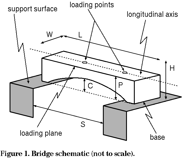
-
The bridge (see Figure 1) must span a gap (S) of 300. mm,
be no longer (L) than 400. mm, have a maximum width
(W) of 80. mm, be no taller (H) than 150. mm
above the support surfaces. The bridge must be constructed to
permit a clearance (C) of 20. mm above the support surface
at the midpoint of the span. No part of the bridge
may extend below the support surface.
-
The loading plane (P) shall be horizontal and shall lie between
30. mm and 40. mm above the support surfaces.
-
The bridge must be constructed to provide for the placement of the
loading plate (see section 3, below) at each of
the two loading points. Any portion of the structure above or
below the loading plane must provide clearance for the loading rod
at the two loading point locations.
3. Loading
-
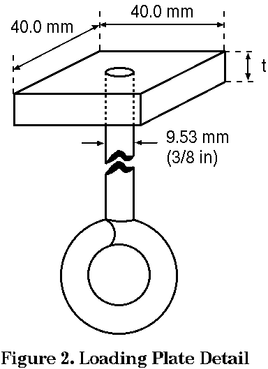
The load will be applied downward, from below, by means of a
40.0 mm square plate (see Figure 2) resting on the loading plane
of the bridge. The plate will be between 6. mm and 13. mm
thick and will have a 9.53 mm (3/8 inch) diameter eyebolt
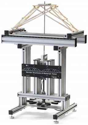
attached from below at its center. Force will be applied to the
loading plate by means of a Vernier Materials Tester shown in Figure
3.
-
The two edges of the loading plate will be parallel to the
longitudinal axis of the bridge at the time of load application.
-
The load will be applied on the longitudinal axis of the bridge at one
of two loading points: 60. mm to one side, and 20. mm to the
other side of the center of the 300. mm span.
4. Testing
-
On the day of the contest, judges will decide the exact loading
location to be used. It will be the same for all bridges.
-
The bridge will be centered on the support surfaces.
-
The loading plate will be placed on the bridge at the specified
loading location and the load will be applied from below, as described
in section 3 above.
-
The load will be applied until bridge failure. The maximum scoring
load supported by any bridge will be 50 kg. Any amount over this
quantity will not count in the calculation of the bridge's
efficiency.
-
Bridge failure is defined as the inability of the bridge to carry
additional load, or a load deflection of 25. mm under the
loading location, whichever occurs first.
-
The bridge with the highest structural efficiency, E, will be
declared the winner. Bridges failing above 50. kg will be
considered to have held 50. kg for efficiency calculation.
E = Load supported in grams (50,000g maximum) / Mass of bridge in
grams
5. Qualification
-
All construction and material requirements will be checked prior to
testing. Bridges failing to meet these requirements will be
disqualified. If physically possible, disqualified bridges may be
tested as exhibition bridges at the discretion of the builder and the
contest directors.
-
If, during testing, a condition becomes apparent (i.e., use of
ineligible materials, inability to support the loading plate, bridge
optimized for a single loading point, etc.) which is a violation of
the rules or prevents testing as described above in Section 4, that bridge shall be disqualified. If the
disqualified bridge can accommodate loading, it may still be tested as
an exhibition bridge as stated above.
-
Decisions of the judges are final; these rules may be revised as
experience shows the need. Please check our web site,
http://bridgecontest.phys.iit.edu
after January 15, 2017, to learn whether any changes have been made.
Last update: January 14, 2017
[ Bridge Contest Home ] [ International Contest ] [ Chicago Regional Contest ]
[ Region Locator ] [ Official Documentation ] [ Other Bridge Links ]
For further information, contact: Prof. Carlo Segre -
segre@illinoistech.edu,
Illinois Institute of Technology
© International Bridge Building Committee, 2024